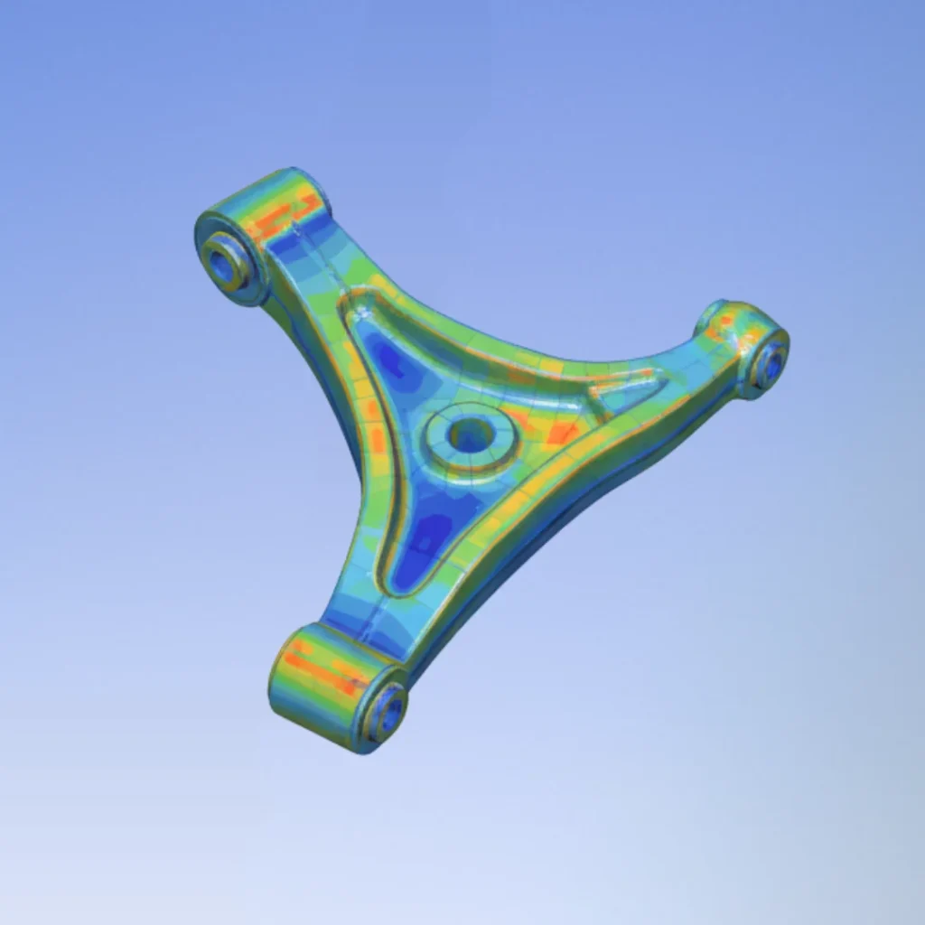
Structural Reliability Audit: Reverse Engineering of Suspension Component
The objective was to take a client’s legacy engineering drawing of an automotive suspension component and perform a detailed structural FEA verification under simulated operating loads. This project utilized 2D-to-3D analytical reconstruction to generate the high-fidelity CAD geometry and ANSYS Static Structural analysis to check critical stress, strain, and Factor of Safety (FOS) metrics, delivering a definitive validation of the component’s structural reliability.
How This Project Took Shape Step by Step
Data Interpretation & Audit
The initial phase involved precise interpretation of the legacy engineering drawing data, translating the 2D views, dimensions, and material specifications into a digital design intent. This audit established the critical structural features and material properties required for accurate simulation setup.
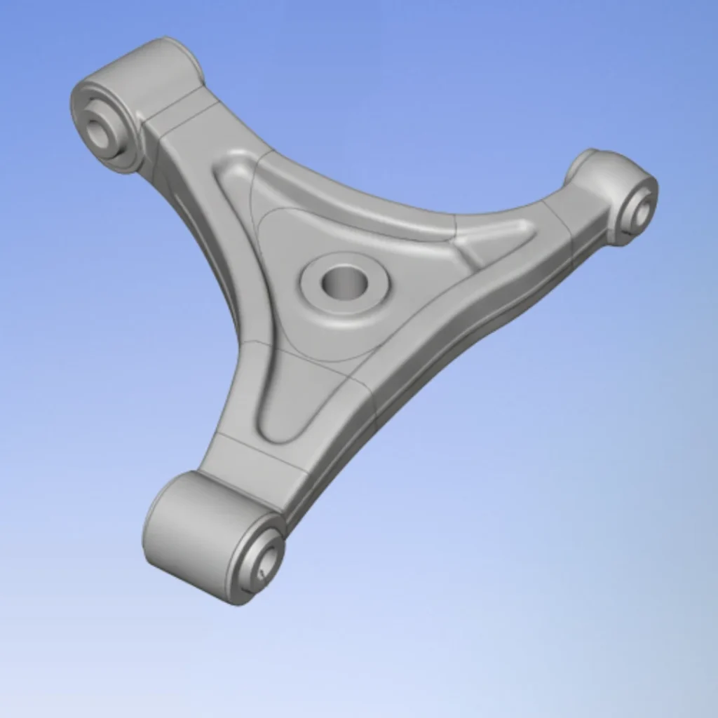
2D-to-3D Analytical Reconstruction
Generated the high-fidelity CAD geometry in SolidWorks directly from the interpreted drawing data. This reconstruction was essential for establishing a reliable digital twin that accurately represented the original component’s complex structural curves and dimensions for subsequent analysis.
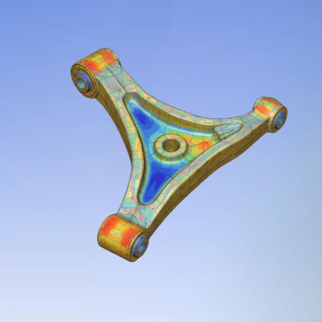
Complex Geometry Meshing
Generated a highly refined finite element mesh, optimizing element size and quality specifically across the critical load-bearing regions and fillets. This preparation was crucial for ensuring the accurate capture of stress gradients during the static analysis without introducing computational error (S_R4).
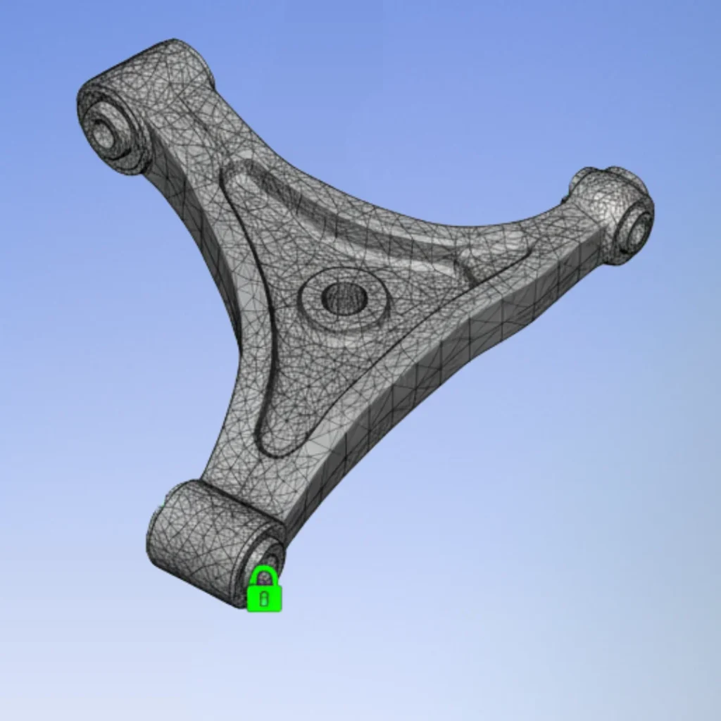
Boundary Conditions Setup
Applied realistic operational constraints derived from automotive standards, including fixed supports at the pivot points and the specified maximum dynamic load conditions. This established the virtual testing environment to simulate the worst-case scenario for structural integrity verification (S_R4).
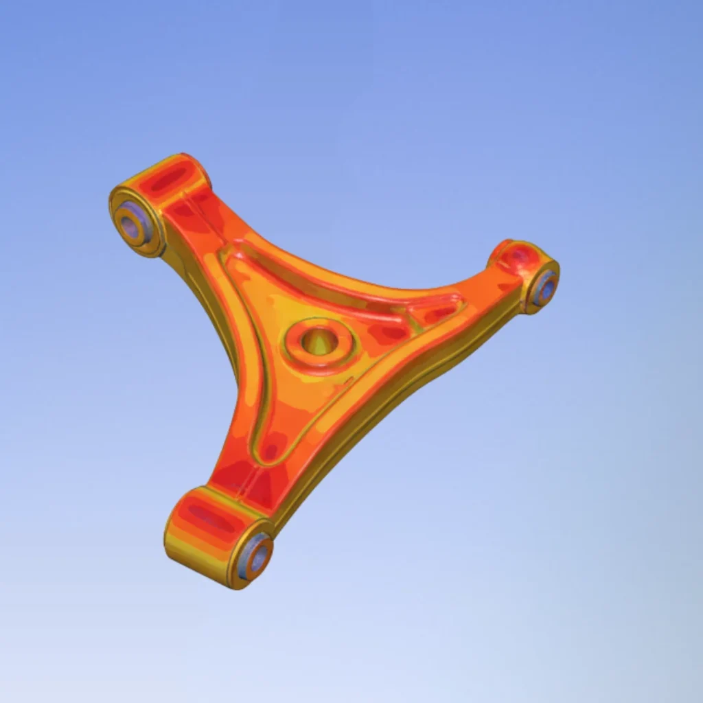
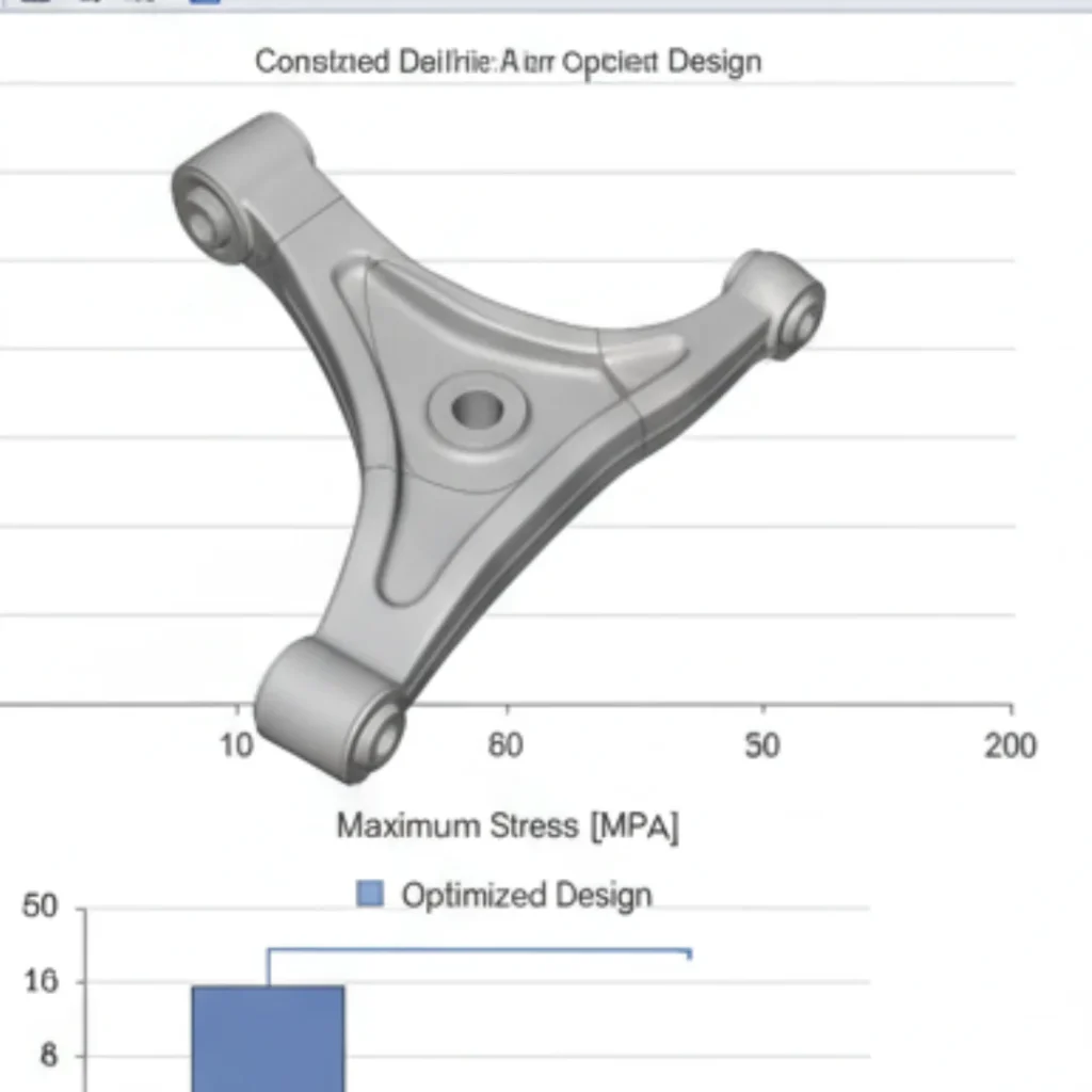
Safety Factor Post-Processing
Executed the ANSYS solver, then extracted and post-processed the critical stress results, calculating the final Factor of Safety (FOS) against the material yield strength. This documented the design’s margin of error and structural compliance (S_R5).
Final Deliverable & Insight
Delivered the complete simulation project files, the verified CAD geometry, and a formal report detailing the structural audit and FOS verification, confirming the component’s structural reliability under extreme conditions.
What the Client Shared About This Project
Every project is complete once the results match what the client envisioned. Here’s their perspective on the process, communication, and final outcome.
For safety-critical components, we need assurance, not just data. The challenge here was working only from old design drawings. The engineer’s expertise in 2D-to-3D analytical reconstruction was flawless, transforming our legacy data into a fully verified digital asset. This process gave us the definitive safety factor required for structural sign-off. Highly recommended expert.

Hana Fujimoto
Automotive R&D Director

Have We Worked Together?
You can share your experience and help others understand what it’s like to collaborate with me on engineering projects.
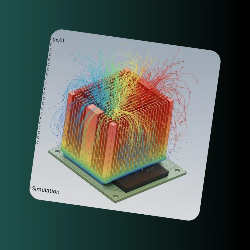
Thermal Management: Optimizing Heat Sink Design for Electronics Reliability
The objective was to design and validate an optimized heat sink to ensure a critical electronic component (e.g., CPU, power transistor) operates within safe thermal limits. This project utilized ANSYS …
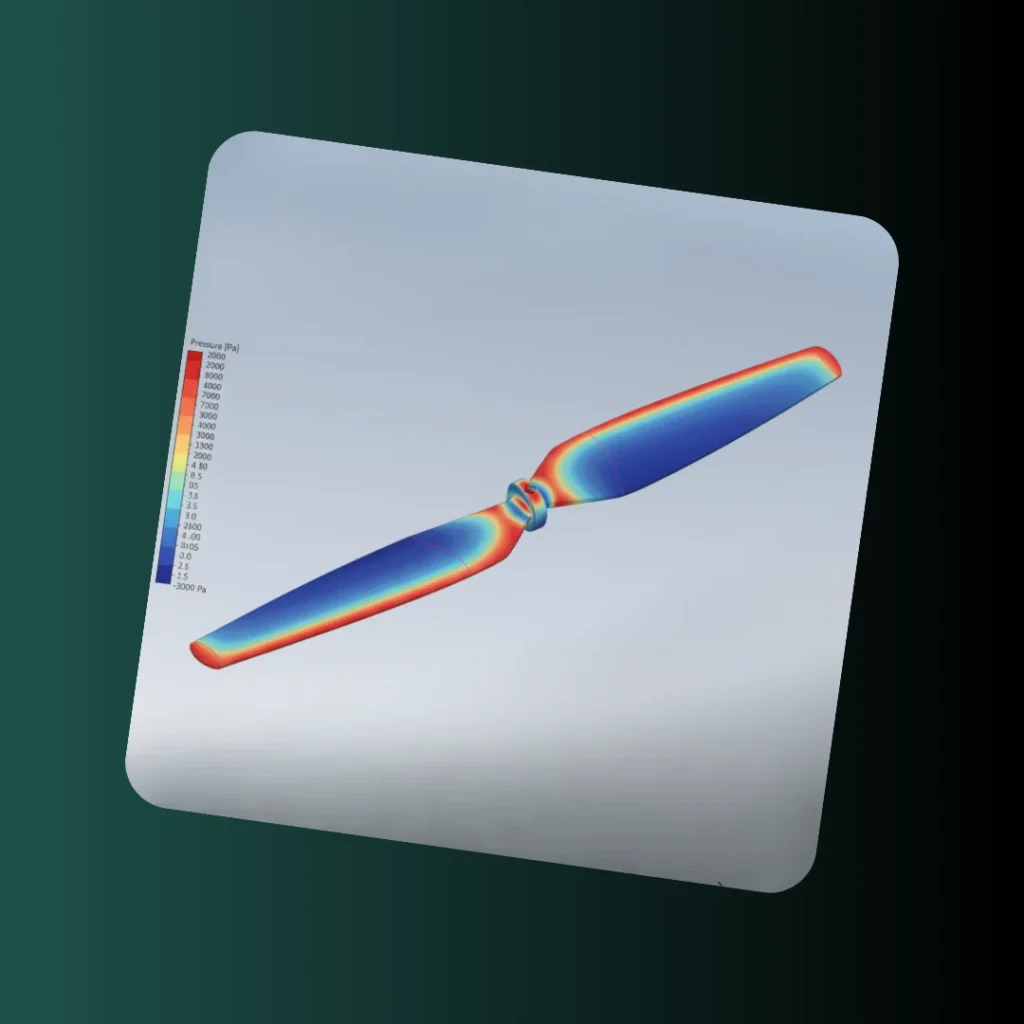
Analysis SoftwareANSYS Steady ThermalThermal ComplianceVerified Max TemperatureCooling PerformanceHeat Dissipation OptimizedFin GeometryDesign Iterations CheckedAerodynamic Optimization: Enhancing Drone Propeller Thrust and Efficiency
The objective was to optimize a drone propeller blade design using advanced CFD analysis to maximize thrust and efficiency under various flight conditions. This project utilized ANSYS Fluent to model …
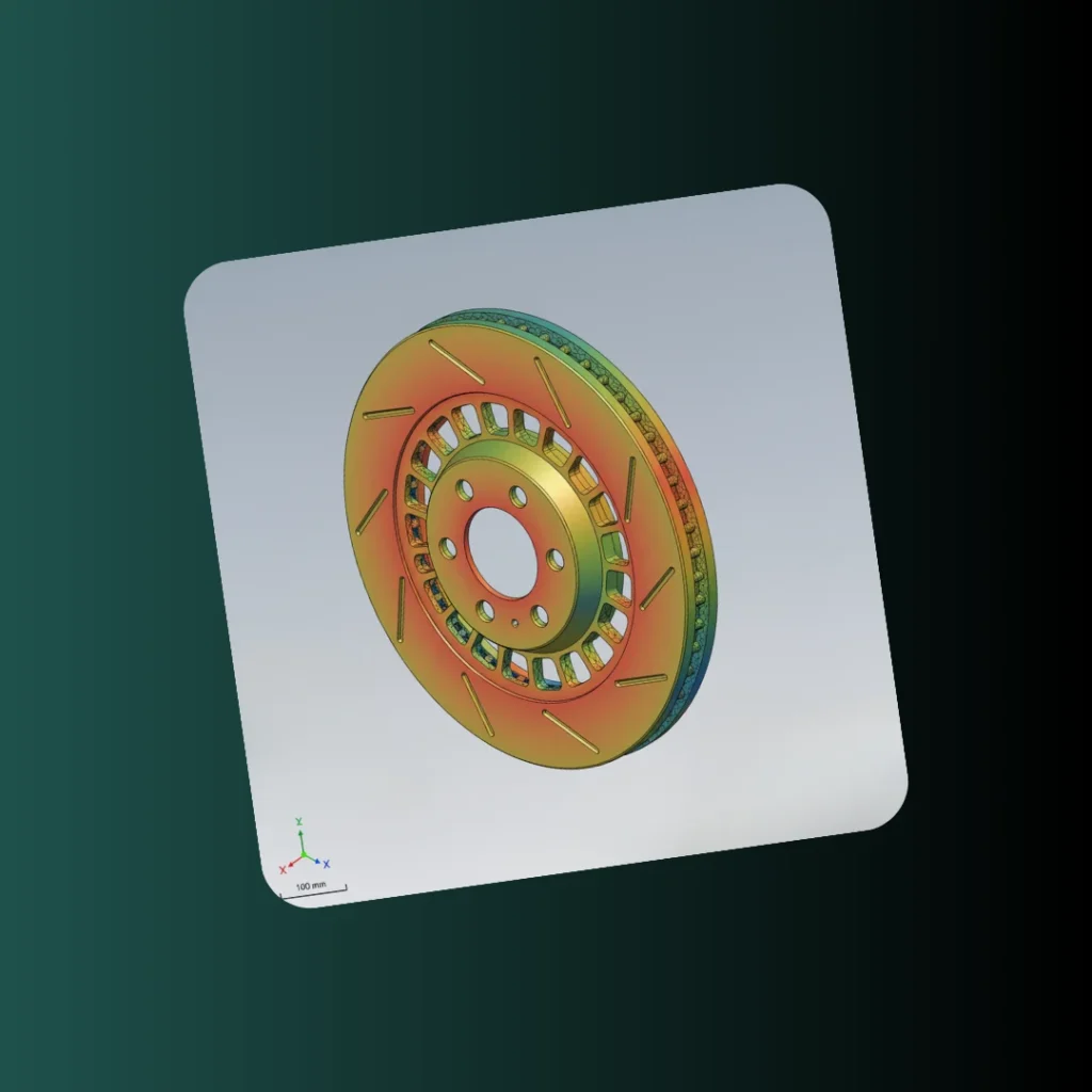
Efficiency GoalMaximize Thrust/TorqueAnalysis SoftwareANSYS Fluent CFDFlow ModelingComplex Airflow SolvedOptimization FocusAerodynamic EfficiencyStatic Structural Analysis: Verifying Automotive Brake Rotor Reliability
The client needed to model their theoretical brake rotor design and verify its performance under maximum load conditions. This project utilized SolidWorks CAD modeling and ANSYS Static Structural analysis to …
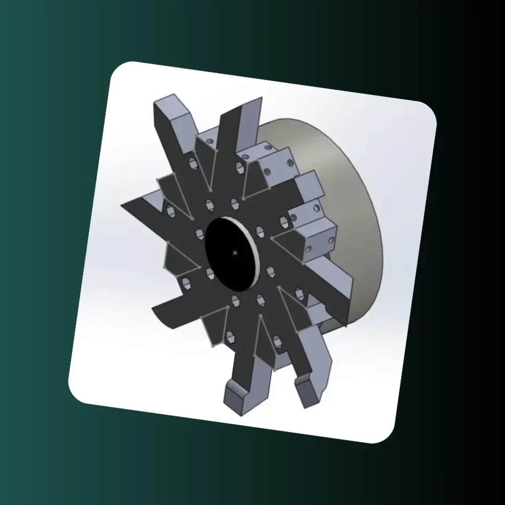
Analysis SoftwareANSYS Static StructuralCritical ResultStress/Strain CheckedReliability MetricFactor of SafetyDesign StatusVerified ReliableCNC Tool Turret: High-Precision Assembly and Indexing Verification
The requirement was to create a precise, high-fidelity 3D CAD model for a CNC machine tool turret assembly, ensuring the accurate rotational mating and precise indexing of multiple cutting tools. …
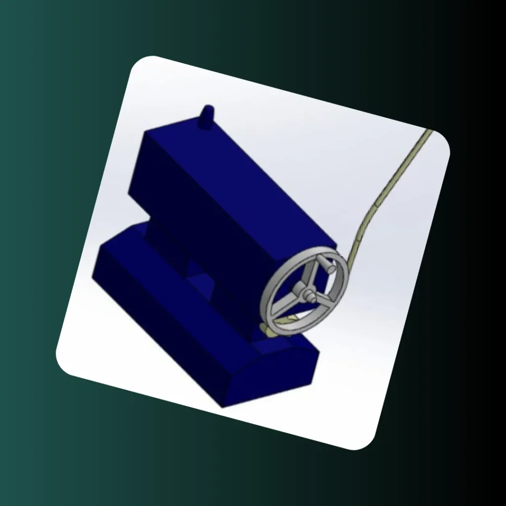
Primary ServicesCAD/DFM / Design ForensicsTool Capacity08 Tool StationsComponent RigidityHigh Structural IntegritySoftware UsedSolidWorks AssemblyHigh-Fidelity CAD: Accurate Parametric Modeling for Visualization
A client required a high-fidelity 3D CAD model of an industrial machine feed mechanism assembly for use in technical archives and presentations. This project focused on precision parametric modeling and …
Software UsedSolidWorks AssemblyAssembly ComplexityAll Mates VerificationModel Flexibility100% ParametricGeometric AccuracyHigh-Fidelity Output
Have a Project in Mind?
If you’re working on a product, simulation, CAD model, or need engineering support, I’d be happy to help you turn it into something precise and functional.