This is just a placeholder headline, we will replace it.

This is just placeholder text. Don’t be alarmed, this is just here to fill up space since your finalized copy isn’t ready yet.
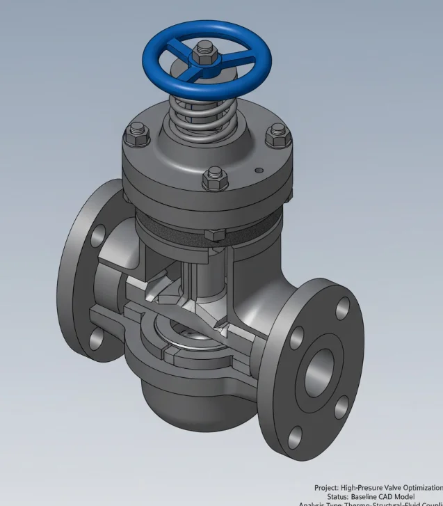
High-Precision CAD Design Built for Manufacturing Success
I create accurate 3D CAD models designed to work in real manufacturing environments. My process blends mechanical logic, geometric accuracy, and DFM practices to make sure every part can be machined, 3D printed, or assembled without unnecessary revisions. Each design is optimized for function, feasibility, and production efficiency, saving time, cost, and effort during prototyping and mass manufacturing.
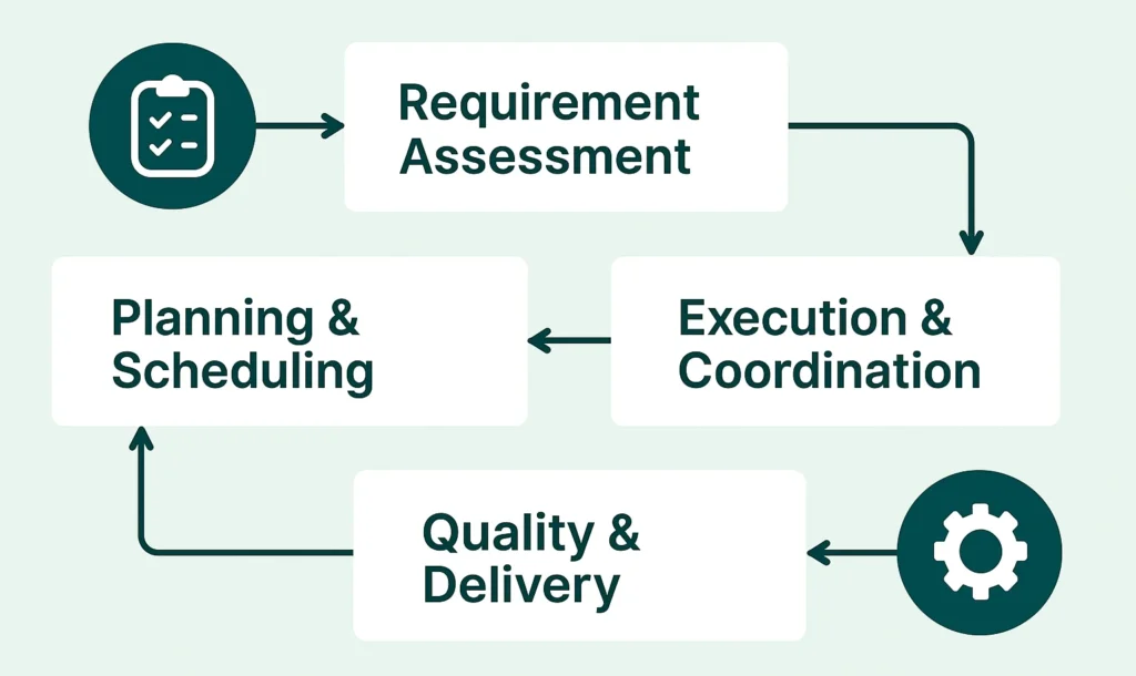
The Integrated DFM Engineering Process: Design to Production
Successful manufacturing requires a system, not just software. This methodology ensures every model moves through rigorous validation, analysis, and optimization before it ever hits the shop floor. My structured approach eliminates costly rework and guarantees the final design is ready for immediate, high-quality production.
Concept Audit & DFM Check
We analyze the concept geometry and material selection against target manufacturing methods (CNC, molding, print), identifying critical DFM issues upfront.
Parametric CAD Modeling
Building robust, associative CAD models using GDT principles. This ensures every component is geometrically sound, easy to modify, and ready for assembly integration.
Precision Verification Matrix
We analyze assembly fits, tolerance stack-up, and critical dimensions directly in the CAD environment to guarantee geometric accuracy and functionality.
Optimization & Refinement
Iteratively adjusting geometry to reduce material cost, improve structural strength, and simplify tooling requirements based on DFM analysis feedback.
CAM-Ready File Delivery
Final delivery includes cleaned geometry, native CAD files, technical drawings (DWG/PDF), and verified output optimized for seamless CAM programming.
Quantifiable Value: Benefits of Manufacturing-Ready Design
Engineering should be an investment, not a cost center. By integrating specialized CAD engineering into the design phase, you systematically eliminate costly errors, streamline production, and gain absolute confidence in your product’s performance and commercial feasibility.
Guaranteed Cost Reduction
Systematically optimize material usage and simplify geometry, directly reducing machining time, material waste, and tooling expenses from the first run.
Manufacturing Risk Elimination
Proactively catch assembly, tolerance, and geometric conflicts before production begins, ensuring zero costly rework or part failure on the shop floor.
Clear, Responsive Communication
Receive consistent, proactive updates and expert answers without delay. The focus remains on making the technical workflow simple and stress-free for your team.
Accelerated Time-to-Market
Deliver CAM-ready design files and verified models that integrate instantly with production pipelines, shortening your lead times and speeding up launch.
Personalized Expertise
You work directly with a dedicated engineer, not a rotating team, ensuring consistency, deep project understanding, and a single point of highly reliable accountability.
Have a Design, Simulation, or CAM Requirement?
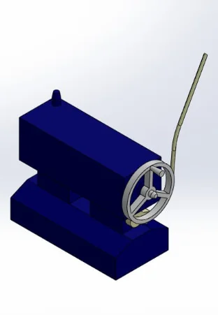
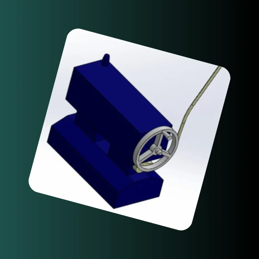
High-Fidelity CAD: Accurate Parametric Modeling for Visualization
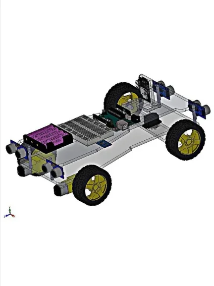
A client required a high-fidelity 3D CAD model of an industrial machine feed mechanism assembly for use in technical archives and presentations. This project focused on precision parametric modeling and …
Software UsedSolidWorks AssemblyAssembly ComplexityAll Mates VerificationModel Flexibility100% ParametricGeometric AccuracyHigh-Fidelity Output
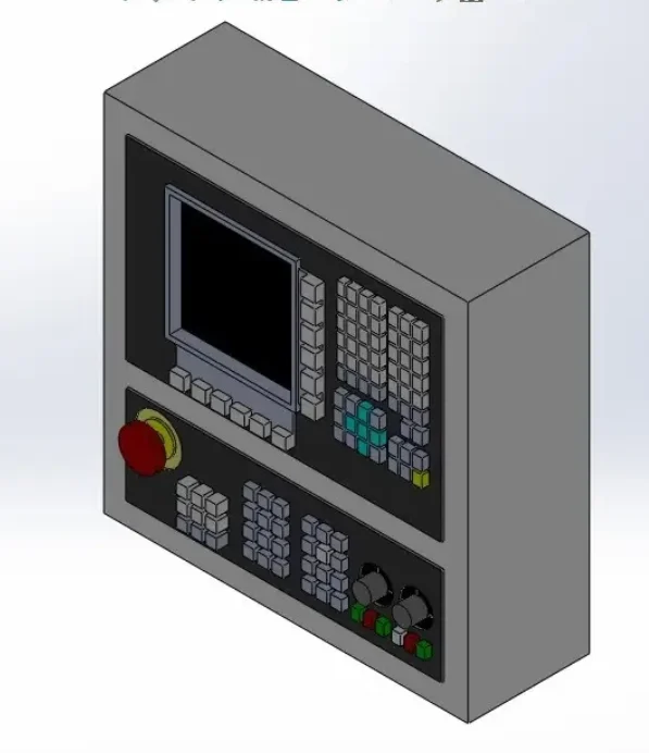
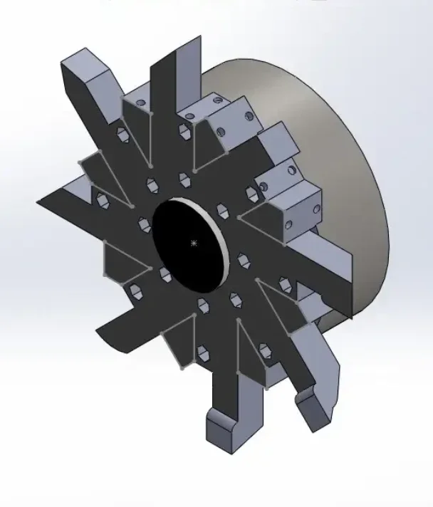
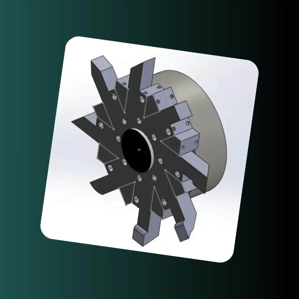
CNC Tool Turret: High-Precision Assembly and Indexing Verification
The requirement was to create a precise, high-fidelity 3D CAD model for a CNC machine tool turret assembly, ensuring the accurate rotational mating and precise indexing of multiple cutting tools. …
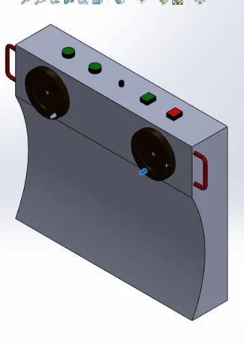
Primary ServicesCAD/DFM / Design ForensicsTool Capacity08 Tool StationsComponent RigidityHigh Structural IntegritySoftware UsedSolidWorks AssemblyStructural Reliability Audit: Reverse Engineering of Suspension Component
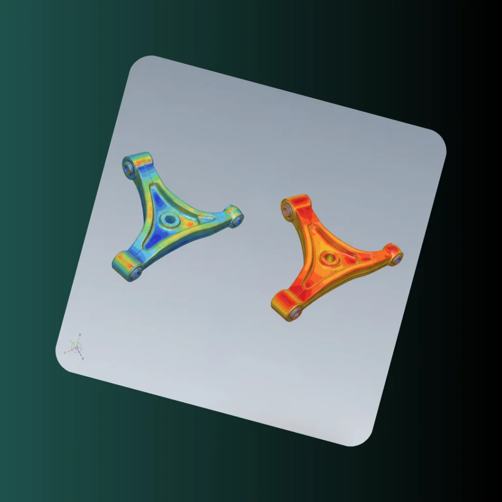
The objective was to take a client’s legacy engineering drawing of an automotive suspension component and perform a detailed structural FEA verification under simulated operating loads. This project utilized 2D-to-3D …
Data OriginEngineering Drawing DataReliability MetricFactor of SafetyVerification MethodSimulated Load TestingDesign StatusVerified Safety Critical
Let’s Clear Things Up
How do you handle tolerance and assembly stack-up issues?
Precision CAD modeling utilizes strict GDT (Geometric Dimensioning and Tolerancing) principles and advanced assembly analysis directly in the software, guaranteeing perfect fit across complex multi-part systems.
Does your service include both 3D modeling and detailed 2D technical drawings?
Yes, every project delivers both the high-accuracy 3D CAD models and fully annotated 2D production drawings (DWG/PDF), complete with necessary BOMs and specifications.
What specific CAD software do you use for design and DFM checks?
I primarily work with industry-standard platforms like SolidWorks and Fusion 360, ensuring your files are fully compatible and ready for any manufacturing environment.
How does this service actually reduce my total manufacturing costs?
By identifying and fixing costly errors like undercuts or improper wall thickness early in the DFM workflow. This systematic optimization reduces machine time, material waste, and the need for expensive tooling revisions.
Can you prepare CAD models specifically for 3D printing or rapid prototyping?
Absolutely. I specialize in optimizing geometry and file output (STL, 3MF) for 3D printing and rapid prototyping, ensuring dimensional accuracy and material efficiency from the initial prototype.
Do you offer revisions if my manufacturing requirements change slightly?
Yes. Revisions within the agreed project scope are standard. Because I use parametric CAD modeling, changes are fast, non-destructive, and integrated smoothly into the final design.
Do you work with both large firms and small startups?
Yes. The precision CAD process is scalable. I support small startups needing rapid prototyping files and larger companies requiring complex, multi-assembly DFM engineering solutions.
What is the fundamental difference between standard CAD modeling and DFM engineering?
Standard CAD modeling focuses on geometry, but DFM engineering focuses on feasibility. It’s the process of proactively auditing the design against real-world material properties, tooling limitations, and manufacturing costs before any physical commitment is made.
How can I ensure my design files are ready for complex CNC machining or injection molding?
The key is using CAM-ready design principles. This requires checking strict geometric continuity, verifying appropriate surface finish, and optimizing minimum radii and draft angles so the model translates cleanly into the CAM software without errors.
When should I hire an external CAD/DFM specialist instead of relying on my internal team?
You should partner with a specialist when the project requires guaranteed precision CAD modeling, especially for complex assemblies or high-volume production. An external expert provides an unbiased, methodical audit, mitigating internal project blind spots and accelerating success.