Aerodynamic Optimization: Enhancing Drone Propeller Thrust and Efficiency
The objective was to optimize a drone propeller blade design using advanced CFD analysis to maximize thrust and efficiency under various flight conditions. This project utilized ANSYS Fluent to model complex air flow, turbulence, and pressure distribution, delivering precise performance metrics and geometry adjustments essential for superior aerial performance.
How This Project Took Shape Step by Step
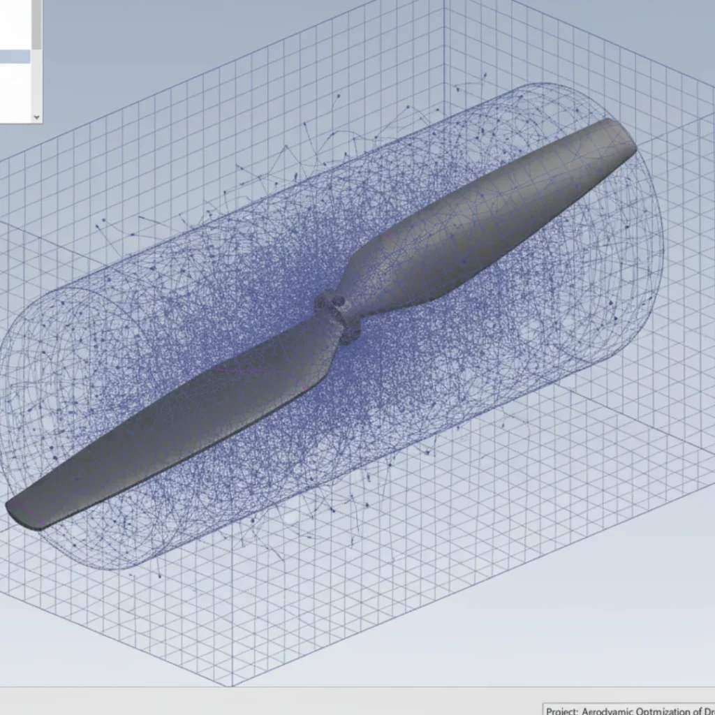
Computational Domain & Meshing
Created a precise computational domain (air volume) around the propeller and generated a high-quality, structured mesh in the rotating fluid zone. This step was vital for capturing the intricate boundary layer and wake flow accurately, ensuring the fidelity of the subsequent aerodynamic analysis.
Fluid Dynamics Setup
Established the necessary boundary conditions, including rotational velocity, inflow speed, and turbulence models within ANSYS Fluent. This careful setup ensures the virtual test environment accurately replicates real-world flight dynamics for reliable performance prediction.
Transient Flow Simulation
Executed the CFD solver to determine the pressure and velocity distribution on the blade surface and in the wake region. This provided the raw data necessary to calculate the generated thrust, torque, and overall propulsive efficiency.
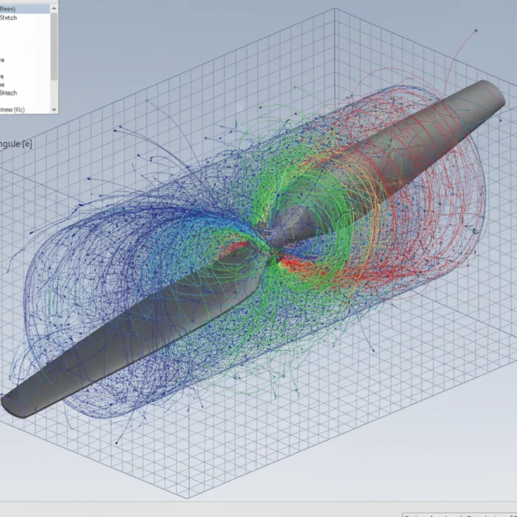
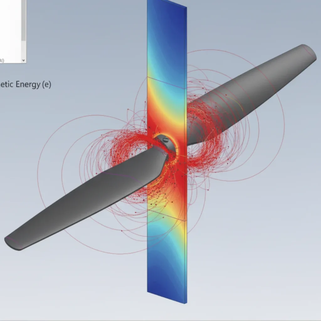
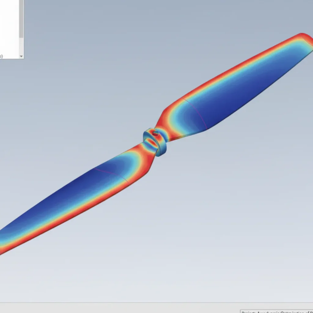
Pressure & Turbulence Analysis
Extracted and analyzed key performance indicators, including the pressure distribution (S_R4) on the blade surfaces and turbulence contours in the wake. This diagnostic step precisely located areas of inefficient flow and unnecessary drag.
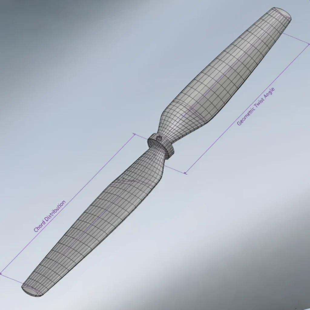
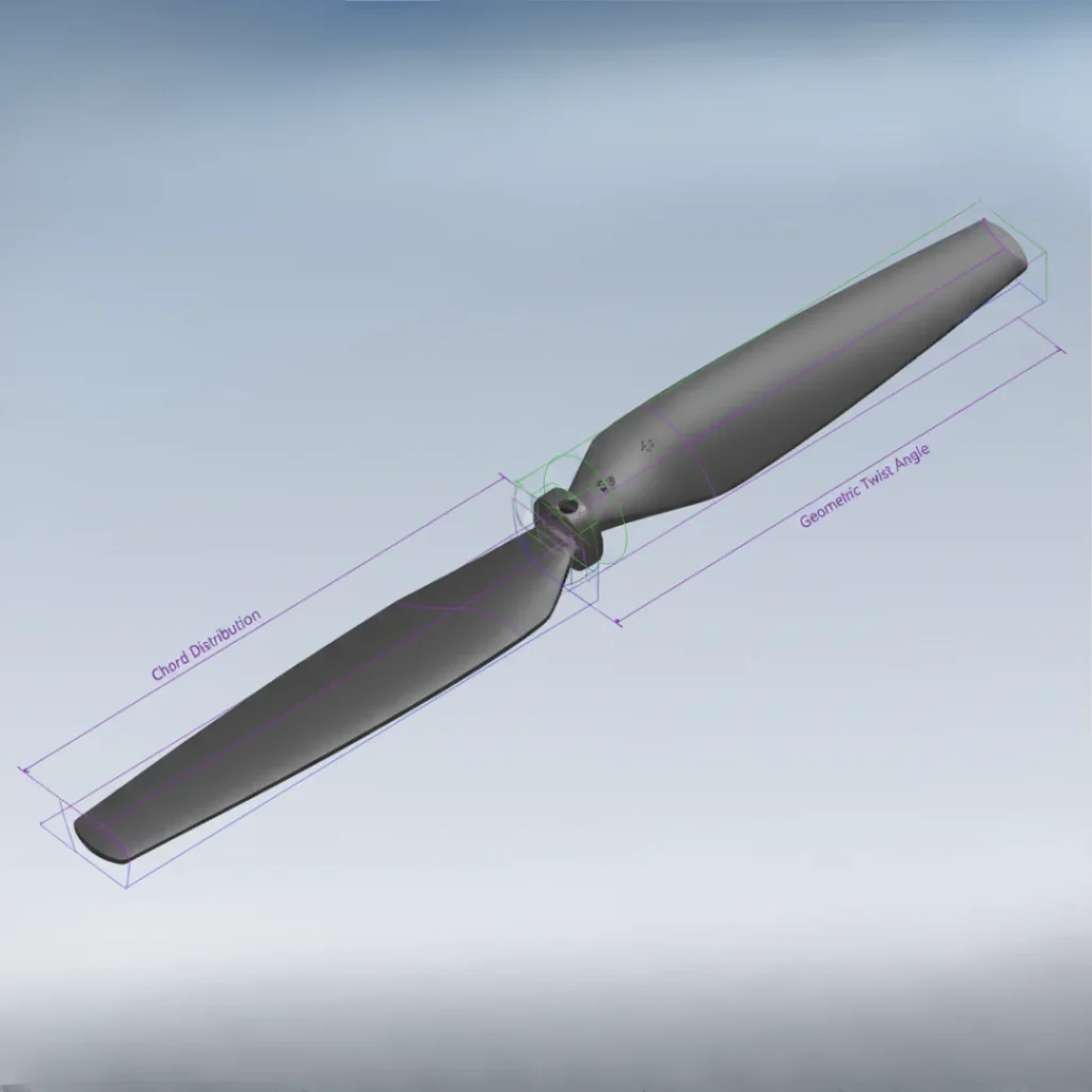
Optimization Iteration
Utilized the analytical data to guide geometric adjustments (e.g., chord distribution, twist angle) on the propeller blade. The iterative process confirmed that the new design achieved the targeted aerodynamic efficiency gains over the original geometry.
Final Efficiency Verification
Delivered a comprehensive aerodynamic optimization report detailing the percentage increase in efficiency and thrust. The final model provided the client with verifiable data for immediate manufacturing and flight testing.
What the Client Shared About This Project
Every project is complete once the results match what the client envisioned. Here’s their perspective on the process, communication, and final outcome.
In the drone market, efficiency is everything. We needed data that was absolutely trustworthy. Touseef’s CFD analysis was strategic, he didn’t just model, he provided verifiable efficiency metrics that justified our design changes. It was a precise, high-level partnership that saved us months of physical testing.

Ama Boateng
Director of Product Development

Have We Worked Together?
You can share your experience and help others understand what it’s like to collaborate with me on engineering projects.
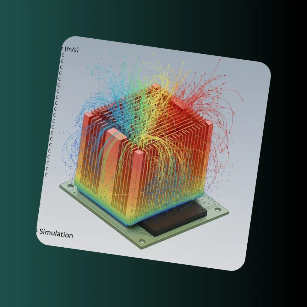
Thermal Management: Optimizing Heat Sink Design for Electronics Reliability
The objective was to design and validate an optimized heat sink to ensure a critical electronic component (e.g., CPU, power transistor) operates within safe thermal limits. This project utilized ANSYS …
Analysis SoftwareANSYS Steady ThermalThermal ComplianceVerified Max TemperatureCooling PerformanceHeat Dissipation OptimizedFin GeometryDesign Iterations CheckedStructural Reliability Audit: Reverse Engineering of Suspension Component
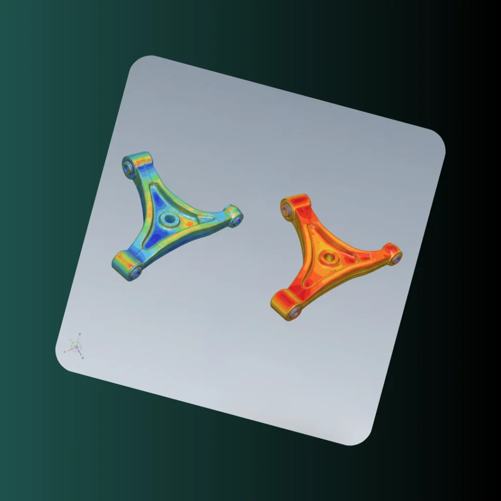
The objective was to take a client’s legacy engineering drawing of an automotive suspension component and perform a detailed structural FEA verification under simulated operating loads. This project utilized 2D-to-3D …
Data OriginEngineering Drawing DataReliability MetricFactor of SafetyVerification MethodSimulated Load TestingDesign StatusVerified Safety CriticalStatic Structural Analysis: Verifying Automotive Brake Rotor Reliability
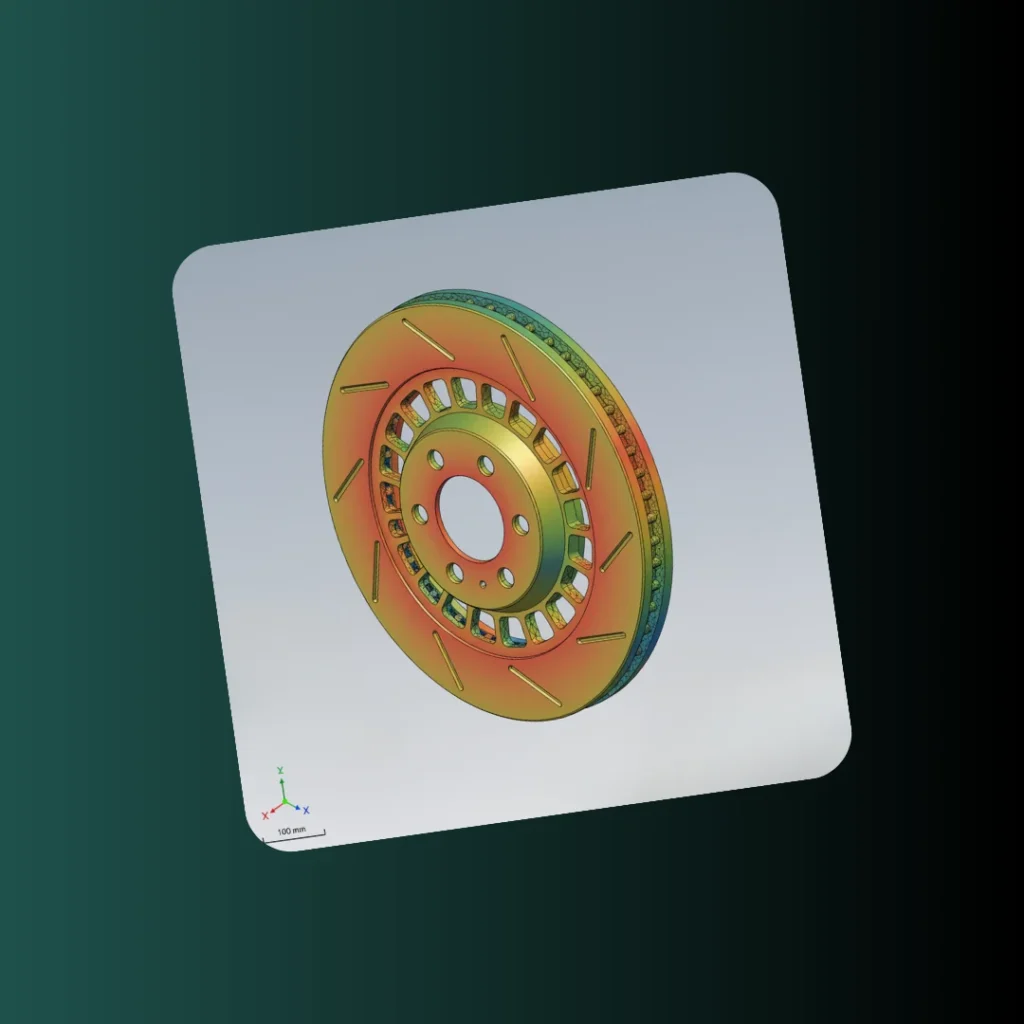
The client needed to model their theoretical brake rotor design and verify its performance under maximum load conditions. This project utilized SolidWorks CAD modeling and ANSYS Static Structural analysis to …
Analysis SoftwareANSYS Static StructuralCritical ResultStress/Strain CheckedReliability MetricFactor of SafetyDesign StatusVerified ReliableCNC Tool Turret: High-Precision Assembly and Indexing Verification
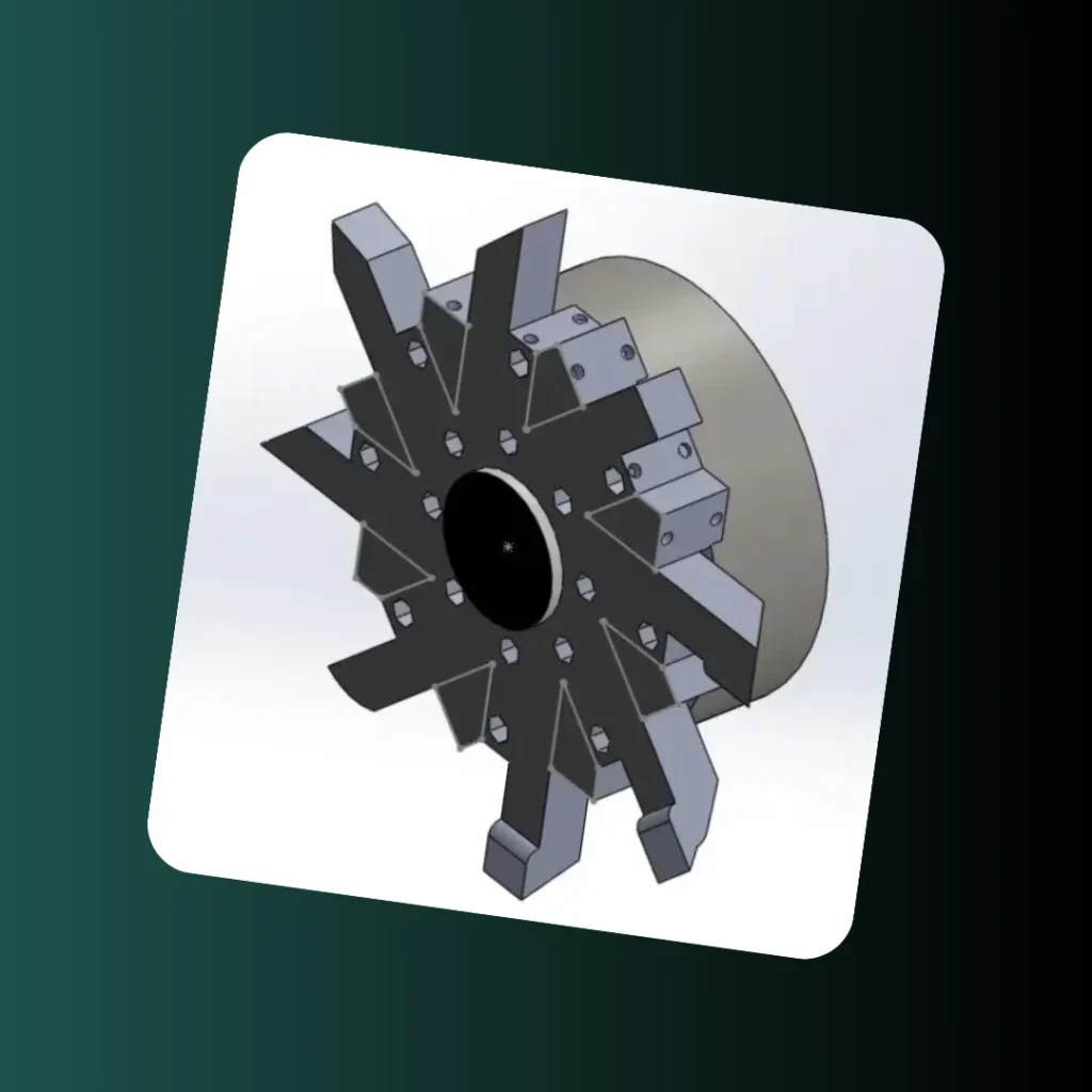
The requirement was to create a precise, high-fidelity 3D CAD model for a CNC machine tool turret assembly, ensuring the accurate rotational mating and precise indexing of multiple cutting tools. …
Primary ServicesCAD/DFM / Design ForensicsTool Capacity08 Tool StationsComponent RigidityHigh Structural IntegritySoftware UsedSolidWorks AssemblyHigh-Fidelity CAD: Accurate Parametric Modeling for Visualization
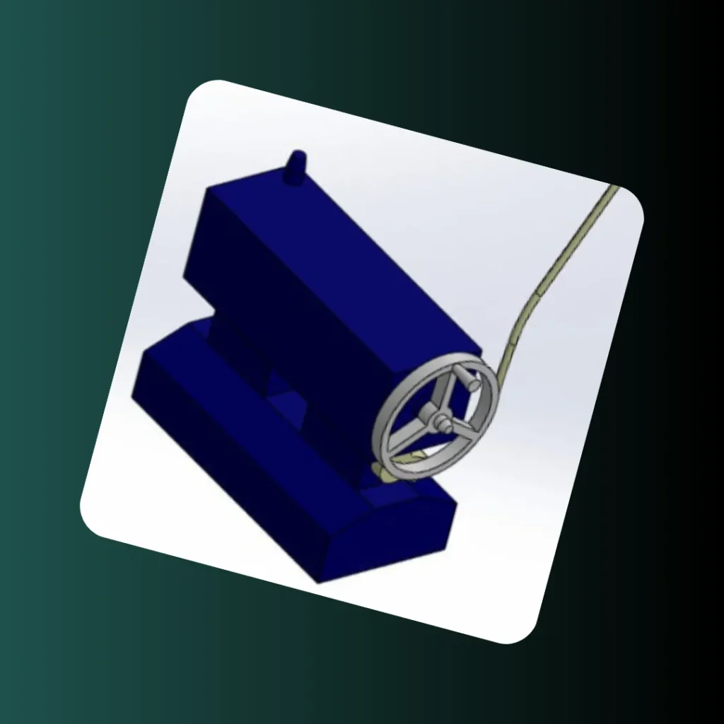
A client required a high-fidelity 3D CAD model of an industrial machine feed mechanism assembly for use in technical archives and presentations. This project focused on precision parametric modeling and …
Software UsedSolidWorks AssemblyAssembly ComplexityAll Mates VerificationModel Flexibility100% ParametricGeometric AccuracyHigh-Fidelity Output
Have a Project in Mind?
If you’re working on a product, simulation, CAD model, or need engineering support, I’d be happy to help you turn it into something precise and functional.